Contents
What Power Factor is?
Introduction
In this article, we are going to understand the concept of what actually the power factor is? But before understanding the concept of the power factor, first, we have to understand the concept of power which is discussed below.
Electrical power as we know the amount of electrical energy that can be transferred to another form of energy such as light, heat, etc. per unit time.
Mathematically we can say that electrical power is the product of voltage drop across the element and the electrical current flowing through it. Unit of electrical power is watt or Joule/second.
In an AC circuit, the inductor and the capacitor both offer a certain amount of impedance which is given by XL = 2∏fL and XC = 1/2∏fC.
In the above said AC circuit the inductor stores electrical energy in the form of magnetic energy and the capacitor stores the electrical energy in the form of electrostatic energy.
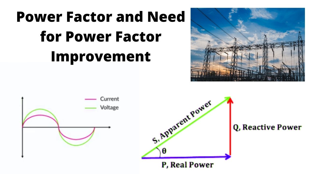
Also, there is a phase shift of 90 degrees between the source voltage and the electric current. Hence when we consider the entire AC circuit consisting of a resistor, capacitor, and inductor then there exists some phase difference between applied voltage and the electric current.
The cosine of the phase difference between the applied voltage and the current is called as Power factor.
The value of the Power factor represents the fraction of the total power that is used to do useful work. And the other fraction of the electrical power is stored in the form of electrostatic energy or magnetic energy in capacitor and inductor respectively.
Total electrical power = Voltage across the element × electric current through the same element
This power is called apparent power or total power. This apparent power is represented by the symbol ‘S’. And the SI unit of the apparent power is volt- Ampere represented by the symbol ‘VA’.
The fraction of the apparent power which actually does our useful work is called active power. This active power is denoted by the symbol ‘P’.
The unit of active power is the watt. And Active power is written as total power multiply by the power factor.
i.e Active power (P) = VI cosφ.
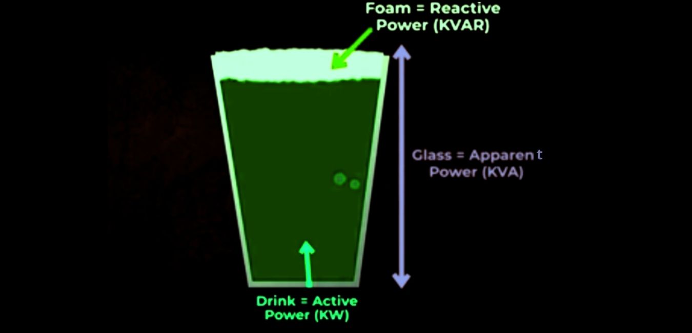
Whereas the other fraction of the total or apparent power is which does not do the useful work but is still required for the active work to be done is called reactive power.
Reactive power is denoted by the symbol ‘Q’ and its unit is VAR (volt-ampere reactive).
Mathematically reactive power is written as
Q = total power × sinφ
Q = V I Cosφ
The reactive power oscillates between the source and load.
For a better understanding of all these power, we will have to understand the power triangle.
Definition
Power factor is defined as the cosine of the phase difference between the applied source voltage and the current in the circuit.
Power factor is also defined as the ratio of the active power to that of the apparent or total power.
It means the power factor is called the fraction of total or apparent power which is utilized to do the useful (active work) work.
Cosφ = Active power / Total power
Need for Power Factor Improvement
We know that Active power is given by P = VI cosφ. So to transfer a given amount of power at a certain voltage, the current is inversely proportional to power factor cosφ.
It means the higher the value of power factor lower (poor) will be the current flowing through the circuit. And due to small current flow, it requires a less cross-sectional area of the conductor and thus saves conductor and cost.
It can be seen from the above relation that the lower value of the power factor increases the flow of current through the conductor and thus copper loss increases.
Further large voltage drop occurs in an electrical transformer, alternator, and transmission and distribution lines which provides very poor voltage regulation.
Due to the high power factor, the kVA rating of the electrical machine can also be reduced.
Reduction in the KVA rating of an electrical machine is done according to the formula,
KVA = KW/ cosφ
As a result of the reduction of the KVA rating the size as well as the cost of the electrical machine is also reduced.
Due to this reason, the value of the power factor should be maintained closer to 1(unity).
Effects of Low Power Factor
- Size (KVA rating) of the equipment (generator) increases.
- Size of the conductor increases as the area increases.
- Increases in power loss (I2R loss).
- The requirement of reactive power also increases.
Different Methods of Power Factor Improvement
| 1. Use of static capacitor |
| 2. Synchronous condenser |
| 3. Phase Advancer method |
Power factor improvement actually means a reduction in the phase difference between the applied voltage and the current flowing through the circuit.
Use of Static Capacitor
As most of the loads in electrical circuits are of inductive nature so they require some amount of reactive power (Q) to perform.
So when we use a capacitor or a capacitor bank installed parallel to the load then this capacitor or capacitor bank thus provides the required reactive power to the load.
As the required reactive power is provided by the capacitor so it acts as a source of local reactive power and thus flows of reactive power through the line is very small.
It means the capacitor actually reduces the phase difference between the voltage and the current.
Synchronous Condenser
Synchronous condenser is actually a Synchronous motor running at no-load conditions in an overexcited region.
In the above condition, the above-discussed motor behaves like a capacitor so a synchronous condenser is also called a Synchronous capacitor.
Synchronous condenser is connected parallel with the supply and it draws the lagging current from the supply or supplies the reactive power to the system and hence improves the power factor of the load.
Power factor is improved in large industries or at larger supply substations by using Synchronous condensers.
Phase Advancer
It is an ac exciter mainly used to improve the power factor of induction motor only.
The phase advancer is usually mounted on the shaft of the induction motor and its supply is connected to the rotor circuit of the motor through the slip rings.
It improves the power factor by providing the exciting ampere turns to produce the required flux at slip frequency. By providing more ampere-turns than the required it can be made to operate at leading power factor and thus improves the power factor of the induction motor.
One of the major disadvantages of the phase advancer is that it is not economical for motors below 200 hp.

Jitu Kumar is the Founder and Senior Content Head of Electrical Maker. On electricalmaker.com, we publish the latest educational updates regarding Engineering.