Contents
Zener Diode as a Voltage Regulator
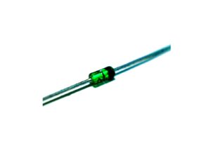
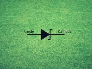
Zener Diode
A Zener diode is a P-N junction diode that is specially designed for operation in the breakdown region in reverse-bias conditions.
Zener Diode, sometimes also called the breakdown diode, is used to take advantage of its sharply defined breakdown voltage when operated in the reverse bias mode.
When a Zener diode works in the forward-bias condition then it works as a normal diode, and in the reverse-bias condition when the applied source voltage is greater than the threshold voltage then the Zener diode suddenly starts operating in the breakdown region.
Talking about the application of the Zener diode, there are numerous applications of the Zener diode in transistor circuits, and the Zener diode as a voltage regulator is one of its applications.
How the Zener Diode Works as a Voltage Regulator
The principle behind the working of the Zener diode as a voltage regulator is the fact that the Zener diode maintains a constant voltage even though the current through it changes.
For proper working of the Zener diode as a voltage regulator, the voltage of an unregulated power supply must be greater than the Zener voltage of the diode selected.
But when the input voltage is less than the Zener voltage, then the diode does not conduct.
Voltage regulation is defined as the measure of a circuit’s ability to maintain a constant output voltage when there is variation in the input voltage or in the load current.
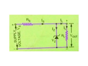
The circuit shown in the figure shows how a Zener diode can be used as a voltage regulator to provide a constant voltage from a source having varying voltage sources.
In the given circuit diagram, a resistance Rs is connect,ed which is necessary to limit the reverse current through the diode to a value.
Zener Voltage and Zener Current
The voltage source VS and the resistor Rs are selected in such a way that the diode operates in the breakdown region.
The diode voltage in this region, which is also the voltage across the load RL is called Zener voltage VZ, and the current that is flowing in the diode is called the Zener Current IZ.
Output voltage fluctuation is absorbed by the series resistor RS so that the voltage across the load can be maintained constant. And the Zener diode is connected across the input voltage whose variations are to be regulated.
As long as the voltage across the load resistor RL is less than the breakdown voltage VZ, then the Zener diode will not conduct, and the resistors Rs and RL will constitute a potential divider across VS.
When the supply voltage VS has increased, then the voltage drop across the load resistor becomes greater than the Zener breakdown voltage, and it then operates in its breakdown region.
The series resistor Rs limits the Zener current IZ from exceeding its rated maximum value IZ max.
Current through the resistor Rs is given by
IS = VS –VZ /Rs
And the current through the source splits at the junction of the Zener diode and the load resistor.
i.e , IS= IZ+IL
When the Zener diode operates in the breakdown region, the voltage across the Zener diode remains constant even though the current flowing through it may vary.
When the supply voltage VS increases, then the current through the Zener diode as well as the load resistance increases.
At the same time resistance of the Zener diode decreases, and the current through the diode increases more than proportionately.
Due to this there will be a greater voltage drop across the series resistor Rs, and the voltage across the Zener diode or load resistance will reach closer to the original value. The reverse case is also true.
In this way, a Zener diode can maintain the output voltage within a fraction of a volt when there is a variation in the supply or input voltage Vs over a wide range of voltages.
As long as the supply voltage is more than the Zener voltage, the Zener diode will maintain a constant voltage across the load.
Let us consider another case of output voltage variation. When the load resistance RL decreases for a constant source of input voltage VS, the load current IL increases.
This increased current is not supplied from the source of supply, but the demand for additional load current is met by the decrease in Zener current IZ.
Due to this, the voltage drop across the series resistor RS is constant, and so the output voltage Vout.
The worst-case occurs for minimum supply voltage and maximum load current because the Zener current reduces to a minimum.
In this case,
ISmin =VSmin -Vz /RS max
Or, RS max = VSmin -Vz /ISmin
As we know that IS = IZ+IL
Then, IZ=IS – IL
In the worst case, the above equation is written as
IZ min = IS min – IL max
When the value of IL max= IS min then the critical point occurs at which the value of Zener current reduces to zero and regulation is lost.
When we substitute IL max in place of IS min, the value of RS max we get is known as the critical resistance.
RS max =VS min – VZ /IL max
Where RS max is the critical resistance, which is the maximum allowable series resistance, VS min is the minimum source voltage, VZ is the Zener voltage, and IL max is the maximum load current.
Zener diode voltage regulator has numerous advantages over other voltage regulators as it is smaller, lighter, more rugged, and has a longer life. It is also simpler and inherently cheaper.

Jitu Kumar is the Founder and Senior Content Head of Electrical Maker. On electricalmaker.com, we publish the latest educational updates regarding Engineering.