Contents
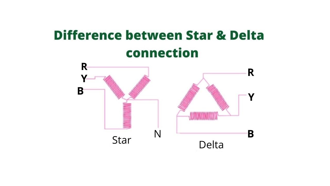
Difference Between Star Connection and Delta Connection
Star & Delta connections are two different configuration methods of the interconnection of the three-terminal of a three-phase system. Both the above said types of connection are discussed below one by one.
Star Connection or Way Connection(Y)
In the star connection method, the similar terminals of the winding say star ends are connected together at one point N as shown in the figure. The point N is called a neutral point or star point.
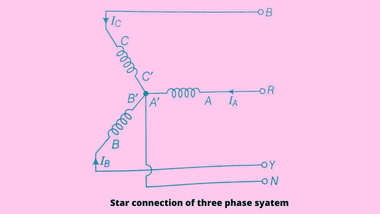
In the given figure A, B and C are the windings of a three-phase system, and IA, IB, and IC are the electric current flowing in the three phases called the line current, therefore for any balanced load value of line current ‘I’L= IA= IB= IC.
It means the current in each line is in series with its individual phase winding hence the line current in each line is the same as the current in the phase winding to which the line is connected.
i.e IL = IP
Where IP = Phase current
Thus in the case of star connection line current is equal to phase current.
Star connection is also called Way (Y) connection.
Line voltage and Phase voltage in Star Connection
Let the emf produced in each phase of the star-connected winding be EA, EB, and EC respectively. EMFs produced here are at a phase difference of 1200 as shown in the phasor diagram.
Here the line voltage is the vector difference between EA and EB and to find the line voltage, EB is extended from the point O till E’B which is of the same length as EB.
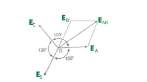
From the phasor diagram, it is clear that points O, EA ,EAB, and E’B form a parallelogram and the resultant of the parallelogram is the vector EAB which the resultant emf.
Then by using parallelogram law we can write,
(EAB)2 = (EA)2 + (E,B)2 +2 EA E,B cos 600
Or, (EAB)2 =E2A + E,B2+ EA E’B (As, cos600= ½)
Let EA= E’B= E (phase voltage)
Then, (EAB)2 = E2 + E2 + E.E
Or, (EAB)2 = 3 E2
EAB = √3 E
Therefore the line voltage EL = √3 EP
Thus from the above equation, we finally concluded that the line voltage in the case of star connection is √3 times the phase current.
i.e EL= √3 EP .
Power in case of star connection
In the case of an AC circuit, the average power consumption is given by the product of supplied voltage and the component of electric current which is in phase with the voltage.
i.e Power in AC circuit is given by,
PAC = V I cos φ
In the case of 1- phase circuit, Power (P) = VP IP cosφ
And in case of three-phase circuit Power is,
P = 3 × power of 1- phase
P = 3 × VP× IP× cosφ
We know that in star connection phase current (IP) = Line current (IL) and phase voltage (VP) = VL/√3
Then power in star connection is
P = 3 × VL/√3 × IL× cosφ
Therefore power ‘P’ = √3 × VL × IL × cosφ.
Delta (∆) Connection or Mesh connection
In this method of interconnection, the dissimilar ends of 3-phase winding are connected together. It means the starting end of one phase is connected to the finishing end of the other phase as shown in the figure.
In the given figure the terminal of the winding A’ – B, B’- C, and C’- A is connected with the phase– R, Phase – Y, Phase-B respectively.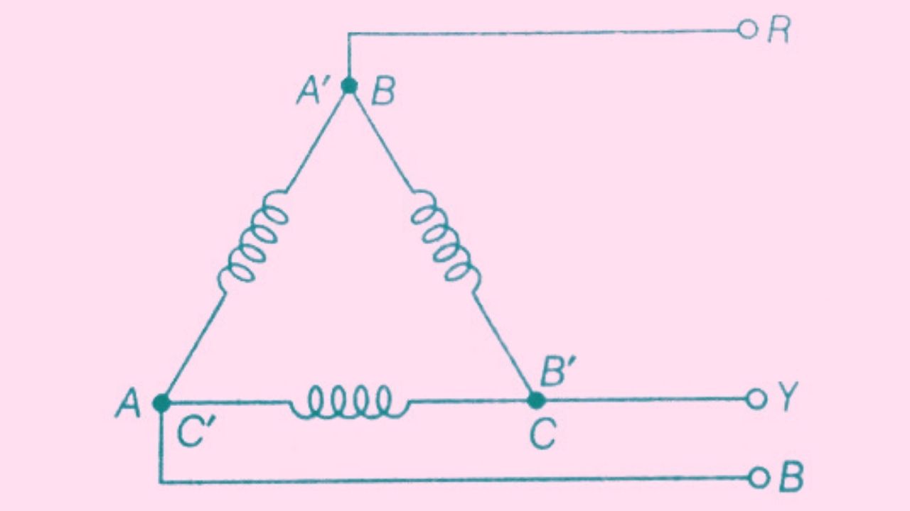
It is also said that the three windings are connected in series to form a closed mesh as shown in the figure. So this delta connection is also called a Mesh connection.
In the case of ∆ connection, the line voltage is equal to phase voltage (for balanced load) because here in the case of delta connection there is no neutral point.
i.e EL = EP
Where EL= line voltage and EP = Phase voltage
Line current and Phase current in Delta connection
Let the emf produced in each phase be EA ,EB, and EC respectively as shown in the figure and these EMFs are at a phase difference of 1200 with each other.
Consider on each phase there is equal and opposite load, then the current IA is in phase with the phase emf EA. Similarly, current IB is in phase with the phase emf EB and IC is in phase with the phase emf EC.
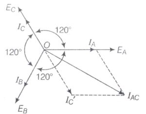
Here in this case line current is calculated as by the vector difference of the current IA and IC for this calculation current IC is extended in opposite direction till IC’ as shown in the phasor diagram. The length of IC’ is the same as that of IC.
By using parallelogram law expression for line current can be written as,
(IAC)2 = IA2 + I2C’ + 2 IA× IC’× cos600
(IAC)2 = IA2 + I2C’ + IA× IC’ [cos600= ½]
Let IA = IC’= I
Put these values in the above equation we get
(IAC)2 = I2+ I2+ I2
(IAC)2 = 3I2
IAC = √3 I
As I = IPhase(Ip)
Then Line current IL = √3 IP
Here from the above result, we can say that in the case of delta connection line current is equal to √3 times the phase current.
Power in case of Delta connection
we know that in the case of delta connection line current IL = √3 IP
and VP =VL
Then power in the case of Delta connection is given by
‘P’ = √3 × VL × IL × cosφ.
Overall it is concluded that there are various parameters on which Star & Delta connections are differentiated. So points of comparison between star and delta connection are discussed below in the table.
Comparison between Star & Delta Connection
| S.NO | Star Connection | Delta connection |
| 1. | Similar ends are joined together. | Dissimilar ends are joined together. |
| 2. | Line voltage is √3 times the phase voltage. | Line voltage is equal to the phase voltage. |
| 3. | Line Current is equal to the phase current. | Line current is √3 times the phase current. |
| 4. | Neutral point is present in this connection. | Neutral point is absent in this connection. |
| 5. | Power (P) =√3 × VL × IL × cosφ. | Power (P) =√3 × VL × IL × cosφ. |
| 6. | In this connection 4-wire 3-Φ system is possible | In this connection, 4-wire 3-Φ system is not possible. |
| 7. | Chances of breakdown are high in this connection. | Chances of breakdown are low in this connection. |
| 8. | Both industrial load and domestic load can be handled. | Only industrial loads can be handled. |
| 9. | This connection looks like Way or Y. | This connection looks like a triangle or ∆. |
| 10. | By earthing the neutral wire relay and protective devices can be provided with the alternator for safety. | Due to the absence of neutral wire, it is not possible in this type of connection. |
Jitu Kumar is the Founder and Senior Content Head of Electrical Maker. On electricalmaker.com, we publish the latest educational updates regarding Engineering.